Manual
Purpose
KKmulticopter Flash Tool is a tool to easily upload a firmware to your KKmulticopter board. It is designed to support the users that never have flashed a firmware to a micro-controller before. You just have to select your programmer and your board or controller type. Afterwards you have the possibility to flash a firmware file from your PC or directly from the internet by selecting from a list of latest available firmwares. This repository is maintained by me, so if I miss a new version please contact me. The tool is saving some settings on the exit of the tool. To not set-up everything on the next launches of the software it saves the settings you did on program end.
General requirements
To run the tool you need a normal Windows PC, Mac or Linux PC. On your machine should be Java installed at least in version 6. You have to be care full when you download it, because the Oracle homepage offers you automatically a download according to the version of the browser that you use. So if you have a 64 bit OS you should also use a 64 bit browser to download Java. Firefox and Chrome are no 64 bit browsers, but IE9 is 64 bit.
Installation
On Windows or Linux
You just have to un-zip the archive you downloaded to any folder you like.
Mac OS X
Just open the dmg-image and move the kkMulticopter Flash Tool to the Applications folder. If you run Mac OS X 10.7 (Lion) you have also to move the libusb 1.0 file to the lib folder. This action will open a password prompt, where you have to enter your password. Before you move the libusb make sure it is not already on your system. Type ls /usr/local/lib/libusb* to the terminal. If it is already there you should find /usr/local/lib/libusb-1.0.0.dylib
Run the flash tool
To start the tool use the run script dedicated for your OS.
- kkMulticopterFlashTool.cmd Windows command script
- kkMulticopterFlashTool.sh Linux bash script
- The kkMulticopter Flash Tool Mac OS App
Do not run the java executable as the tool will not work properly.
The Menu
Settings
The settings menu has one functions:
- you can set the user language.
Contribute
In this menu you can send me a bug report.
The send bug report menu item will open your default email program and paste the content of kklogging.txt to the mail body.
Help
In this part of the menu I collect some internet links to helpful resources to set-up the firmwares I have in the repository and there is a link to this manual.
Info
Contains the About screen and the full text of the GPL 3 license.
Hardware Test
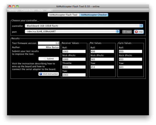
The hardware test abilities of the kkflashtool can be found on the KKMulticopter Checker tab. It is based on the kkcheck V1.0 firmware of Mike Barton. For using the functionality of this module you have to flash the mentioned firmware to the kkboard you want to test. The board's health will be read via a serial adapter and results of the sensors, pot positions and receiver pins can be read on the middle panel of the module.
Requirements
- The driver for the adapter must be installed on your system.
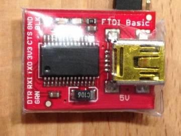
- FTDI VCP driver (Sparkfun basic)
Preparing the hardware
- Flash the kkcheck firmware to your kkboard.
- Set the pots to middle position.
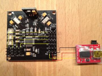
- Connect the motor outputs M1→M4 to the receiver input pins on the kkboard using the male-to-male wires.
- Connect the RX pin on the TTL cable to the signal pin of M6 on the kkboard. Do the same for GND and 5V.
- RXI pin on Sparkfun Basic
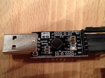
- TXD pin on the CP2102 shown on the image above.
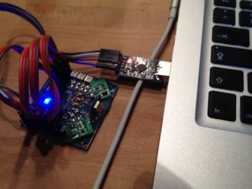
- Plug the USB end into the PC
Running the test
- Switch to the kkMulticopter Checker panel
- Select the board you want to test. This is only for information at the moment and is only required if you submit your results.
- Now plug the USB adapter to the PC. LED on the kkboard should begin to blink.
- Select the serial port from the list.
- Press start to run the test.
- After about one second the results of the test appears in the panel named 'Results'. The data are updated every second until you press the stop button.
Understanding the output
Pot Values
The value shows the gain pot setting (range 0 to 1023). Turning the gain pot should change the value.
Gyro Values
This values show Gyro output. These will typically be in the range 700 to 900 (but may be lower depending on the type of gyro) and will naturally fluctuate by a small amount. Turning the board should produce different numbers, if not there is a problem.
Receiver Values
This number should be 1000 +/-2.
If the value is 0, switch the receiver wire with one of the other receiver wires.
If the problem stays with the receiver pin, it is the receiver pin connection.
If the problem moves, the problem is with the motor output pin.
Submit button & Visit instructions button
Submit button
You may send the results of the test to me, with a comment what a brief description of the symptoms or if it is okay. Make sure the board is selected correctly. I will use the data to improve the Health panel.
Visit instructions
This button links to this page.
